
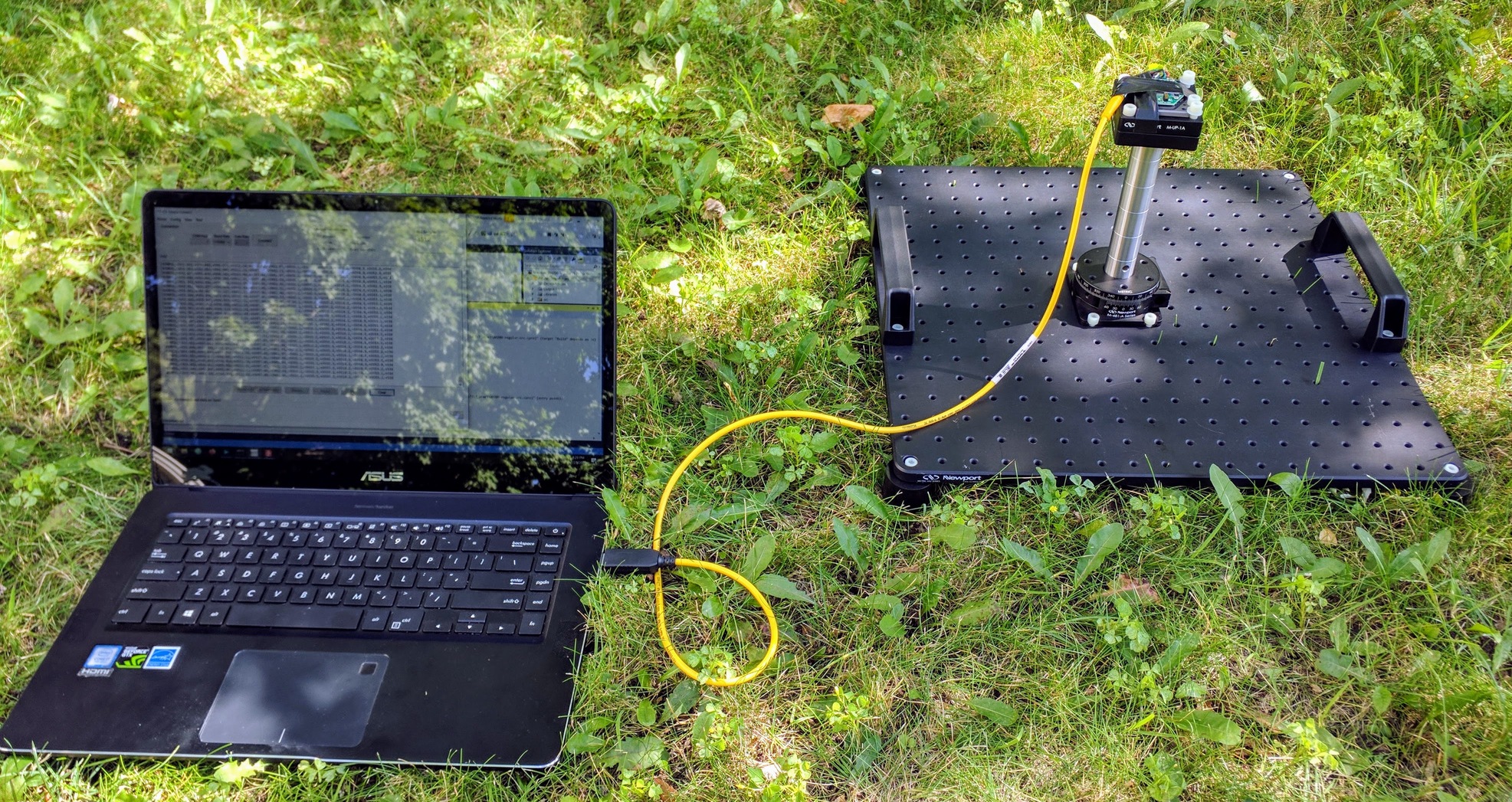
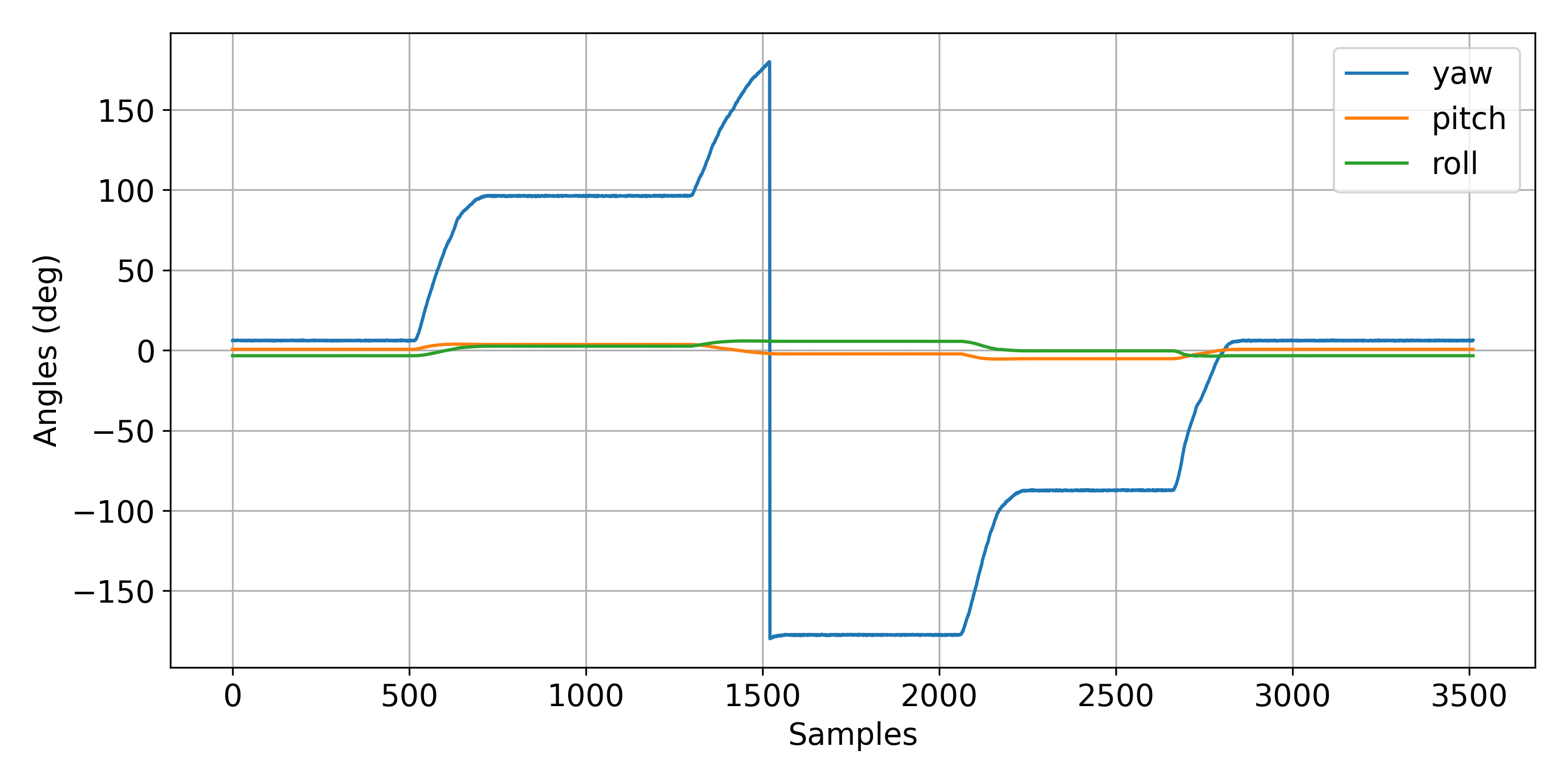
The objective of the heading data collection is to log the Device Under Test (DUT) heading output while putting the device through a sequence of four 90-degree rotations:
The instructions below recommends 20-seconds at each angle and 10-seconds for transfer. Therefore the logged data will cover an approximate 140 seconds (the last 20-seconds covers the 360-degree ). A sample plot of the data collected is given below.
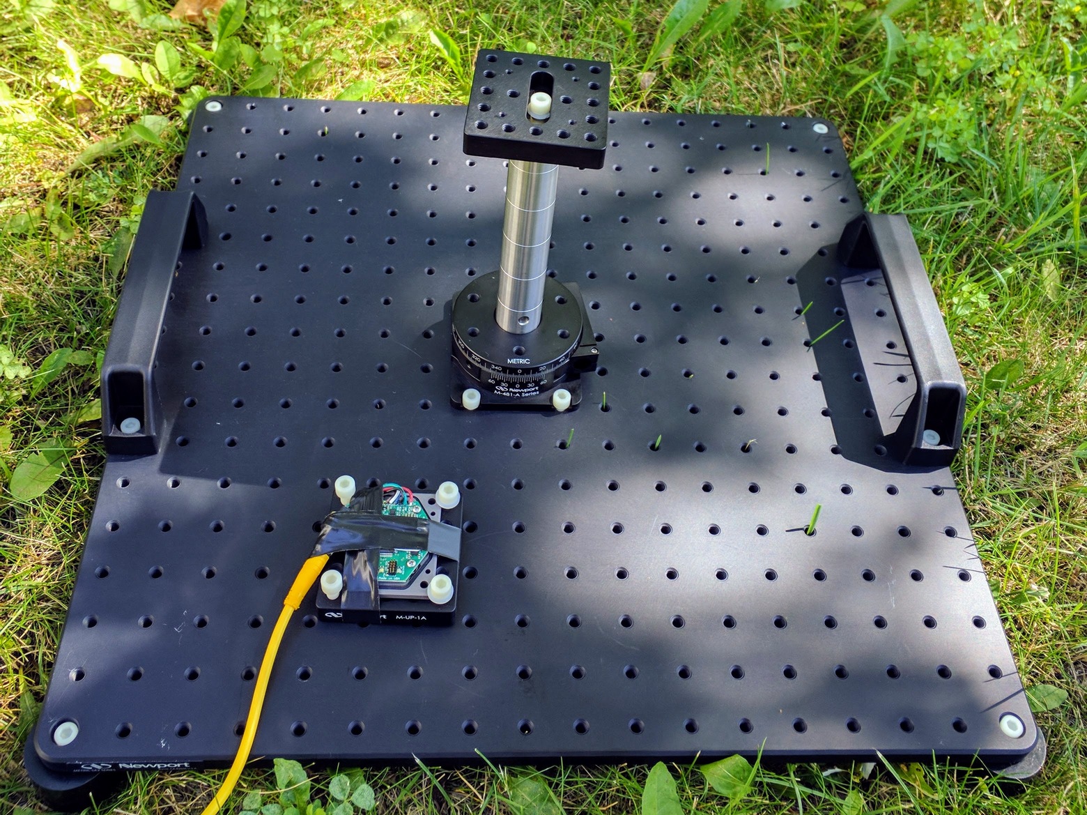
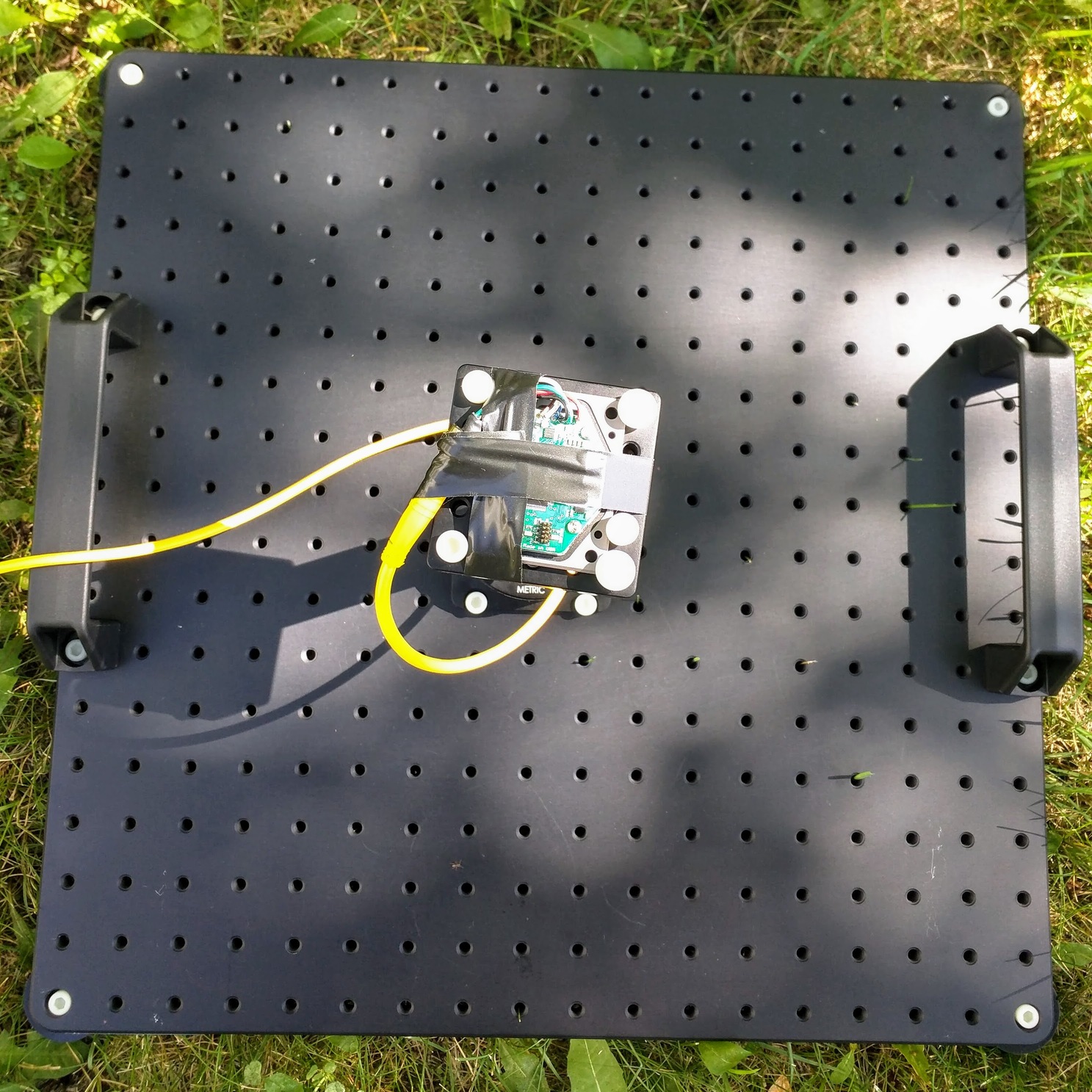
Any parts which are in close proximity to the sensor and have ferrous content should be fixed with respect to the DUT. For example, connectors or cable heads sometimes need this treatment. This is true during calibration, device testing, as well as when leveraging the device in the field. Neglecting to do so will allow the ferrous material to move and impact the local magnetic field. This will degrade magnetic-heading accuracy.
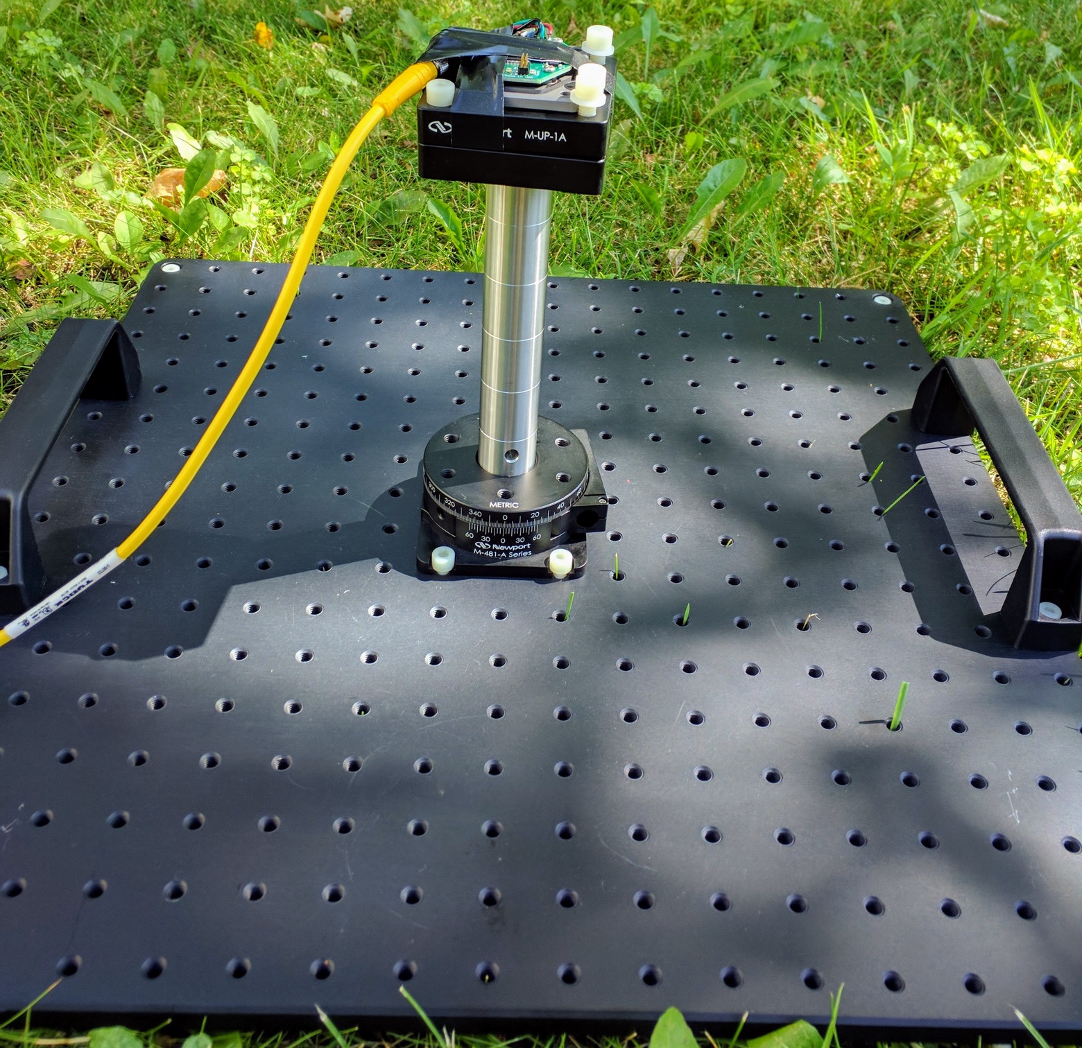
Ensure a rigid installation so that the DUT and the rotation stage experience the same motion.
The DUT may output a non-zero heading estimate in this configuration. The zero-degree setting generally does not correspond to any reference north (e.g. magnetic of true). To achieve such a absolute reference would require aligning the rotation stage 0 deg and the DUT forward-axis (e.g. x-axis) with the desired north reference (e.g. magnetic north). Such an alignment is non-trivial, and furthermore, establishing the north reference requires additional equipment or information.
The heading test described is a relative-heading test. Therefore it is not required to establish a north reference, and furthermore, it is unnecessary to align the DUT forward axis with the rotation stage 0-degree setting.
Avoid touching or bumping the test hardware once data collection has begun. At a minimum, the data to be logged should include the DUT heading, pitch, and roll estimates. A sampling rate of 25 Hz is generally sufficient.
If possible, it is useful to log raw sensor data as well (e.g. magnetometer, gyroscope, and accelerometer). This data can be used to investigate any anomalies observed in the test results.
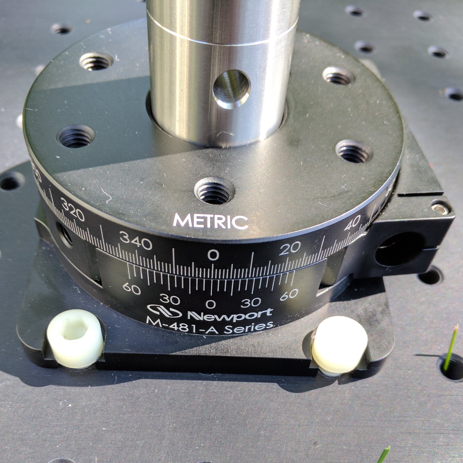
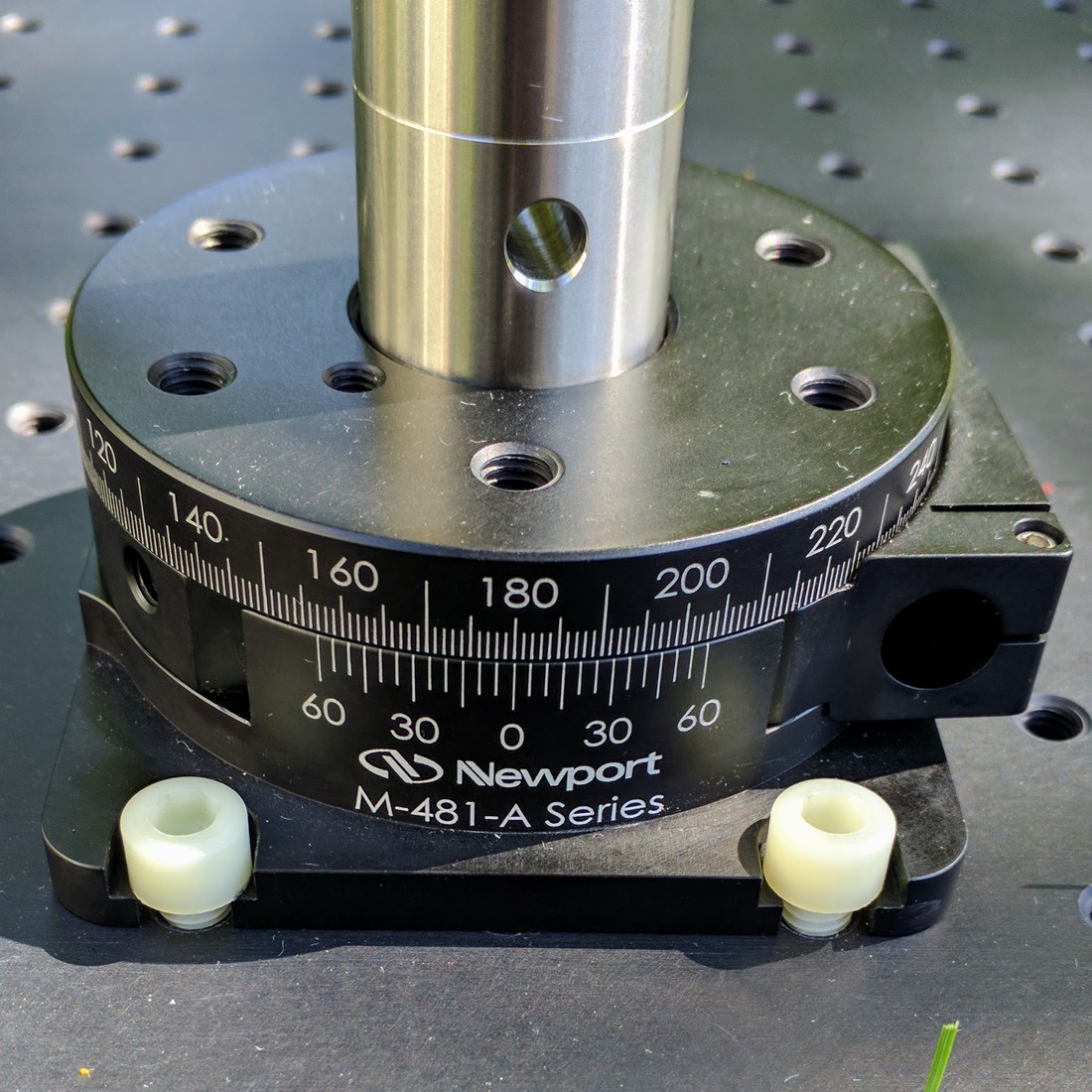
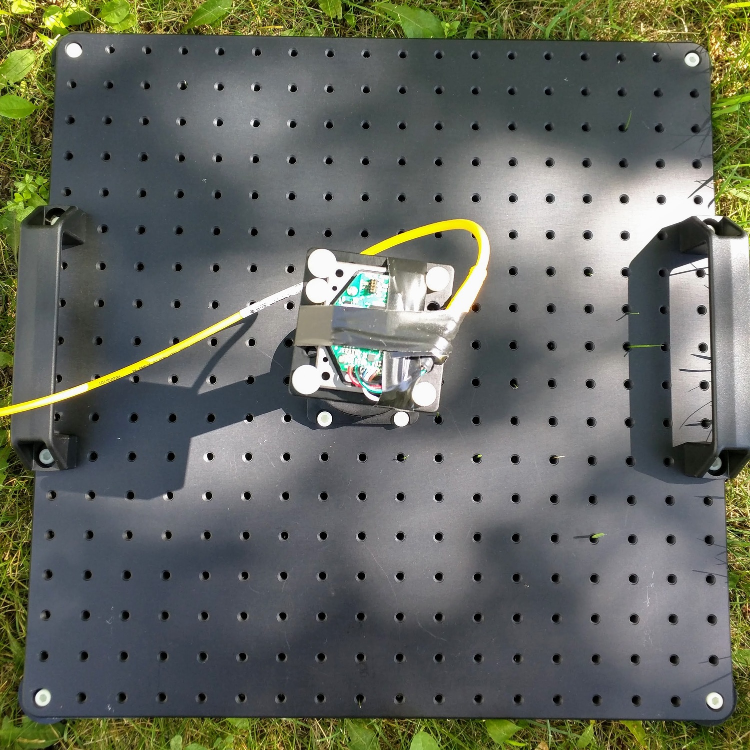
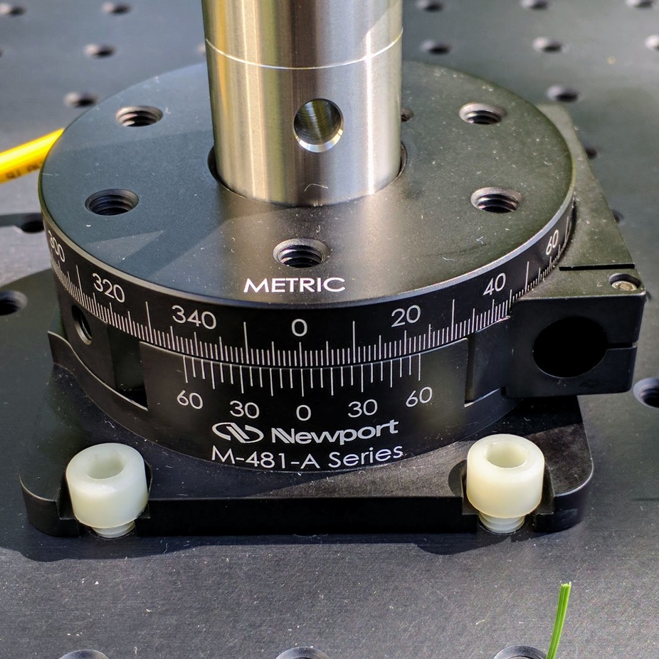
| Rotation stage angle setting | Top-down view of DUT |
|---|---|
|
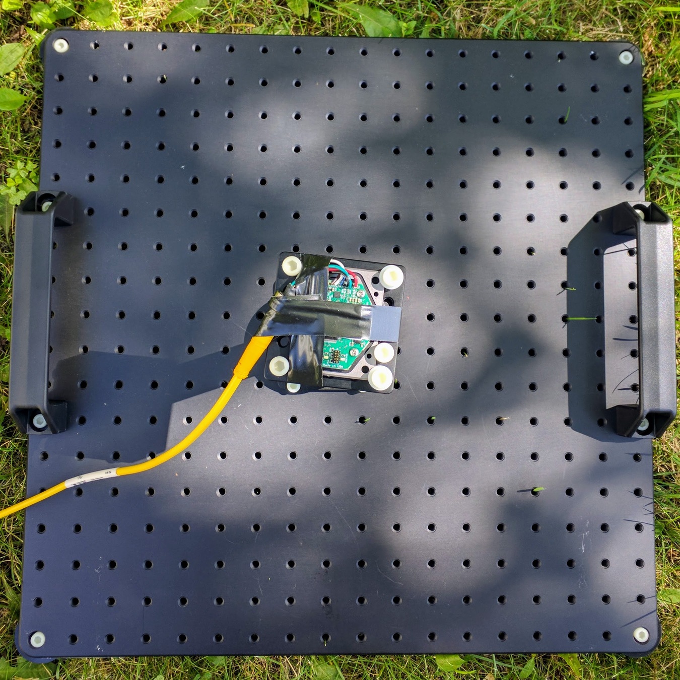 |
Maintain the static 0-degree configuration for 20 seconds. Use the next 10-seconds to slowly but continuously transfer to the next rotation stage angle.
The manual rotation of the rotation stage to the next angle setting should ideally happen in a continuous motion. Try to avoid stopping before the arriving at the next angle setting and also avoid overshoot, which would then require rotating in the opposite direction. Cleaner motion will facilitate easier interpretation of the results.
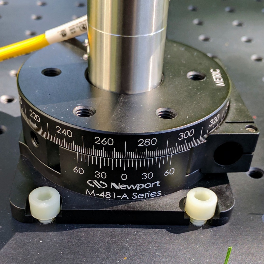
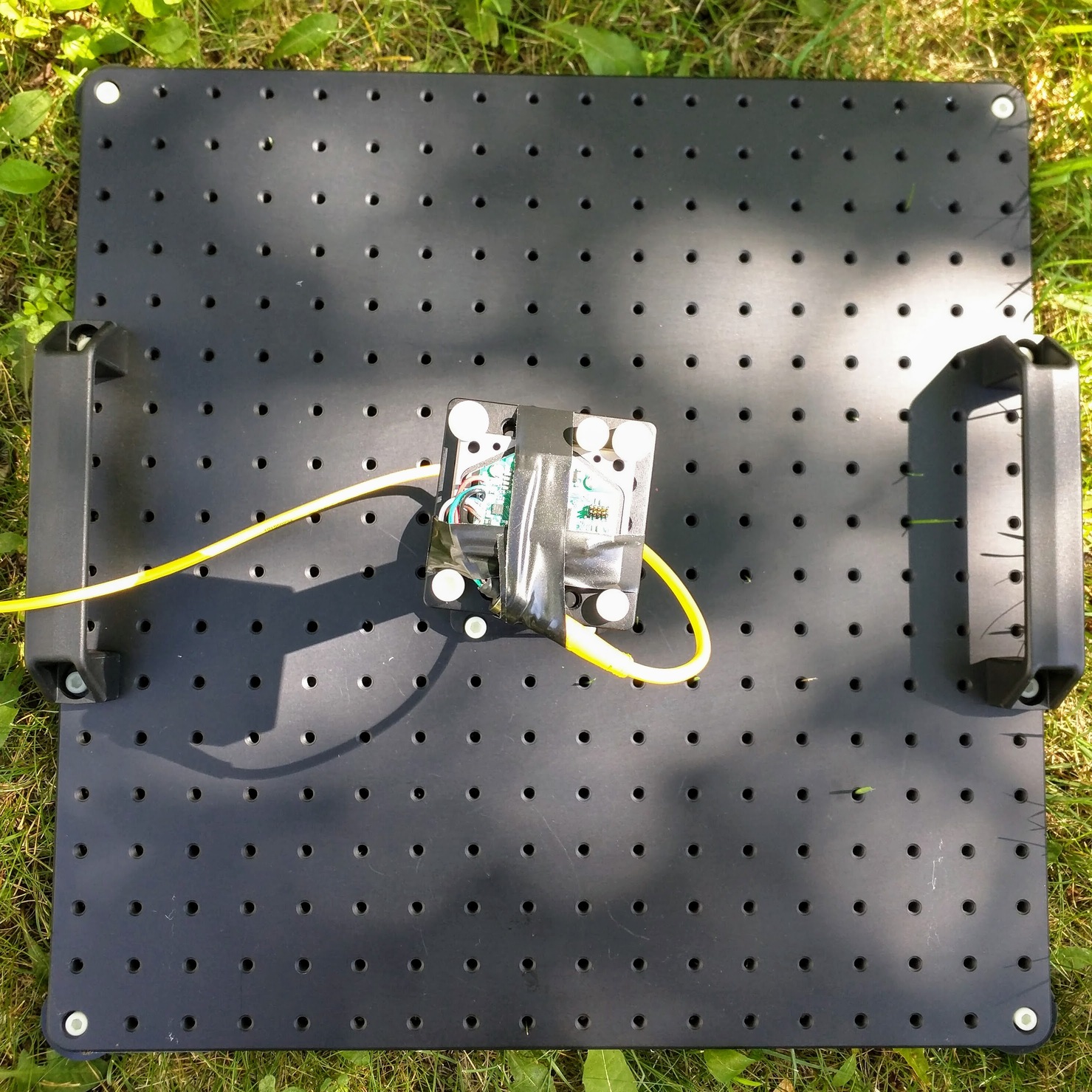
| Rotation stage angle setting | Top-down view of DUT |
|---|---|
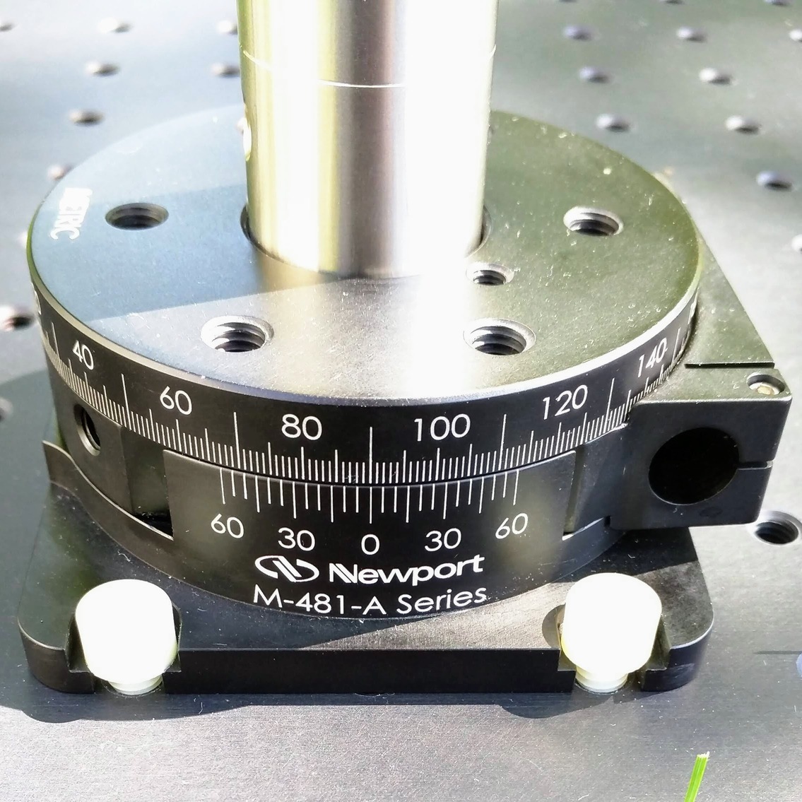 |
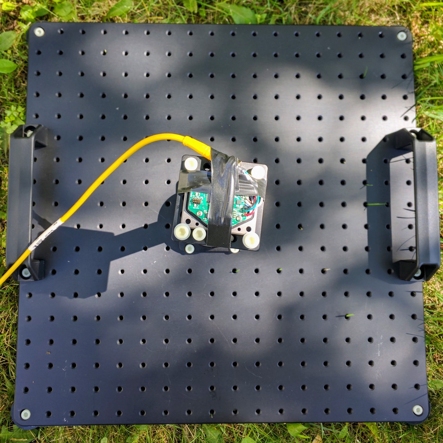 |
Maintain the static 90-degree configuration for 20 seconds. Use the next 10-seconds to slowly but continuously transfer to the next rotation stage angle.
| Rotation stage angle setting | Top-down view of DUT |
|---|---|
 |
 |
Maintain the static 180-degree configuration for 20 seconds. Use the next 10-seconds to slowly but continuously transfer to the next rotation stage angle.
| Rotation stage angle setting | Top-down view of DUT |
|---|---|
 |
 |
Maintain the static 270-degree configuration for 20 seconds. Use the next 10-seconds to slowly but continuously transfer to the next rotation stage angle.
| Rotation stage angle setting | Top-down view of DUT |
|---|---|
 |
 |
Maintain the static 360-degree (i.e. back to 0-degree setting) configuration for 20 seconds.
Save or export the DUT data file into a general format (e.g. CSV) together with applicable metadata. This data file will be used in the heading analysis to quantify the relative-heading performance.
The following metadata is generally recommended to be saved with the data file: