
| Line | Image | Name | Manufacturer | Manufacturer Part No. | Quantity | Description |
|---|---|---|---|---|---|---|
| 1 |  |
Rotation Stage | Newport | M-481-A-S | 1 | 360° Coarse, 5° Fine, Includes Adjustment Screw, M4 and M6 |
| 2 |  |
Optical Post | Newport | M-PS-6E-T | 1 | Peg Base, 152.4 mm Height, 25.4 mm Diameter, M6 Thread |
| 3 |  |
Mounting Plate | Newport | M-UP-1A | 2 | Universal, 65 mm x 65 mm x 12.7 mm, M6 Thread, Metric |
| 4 |  |
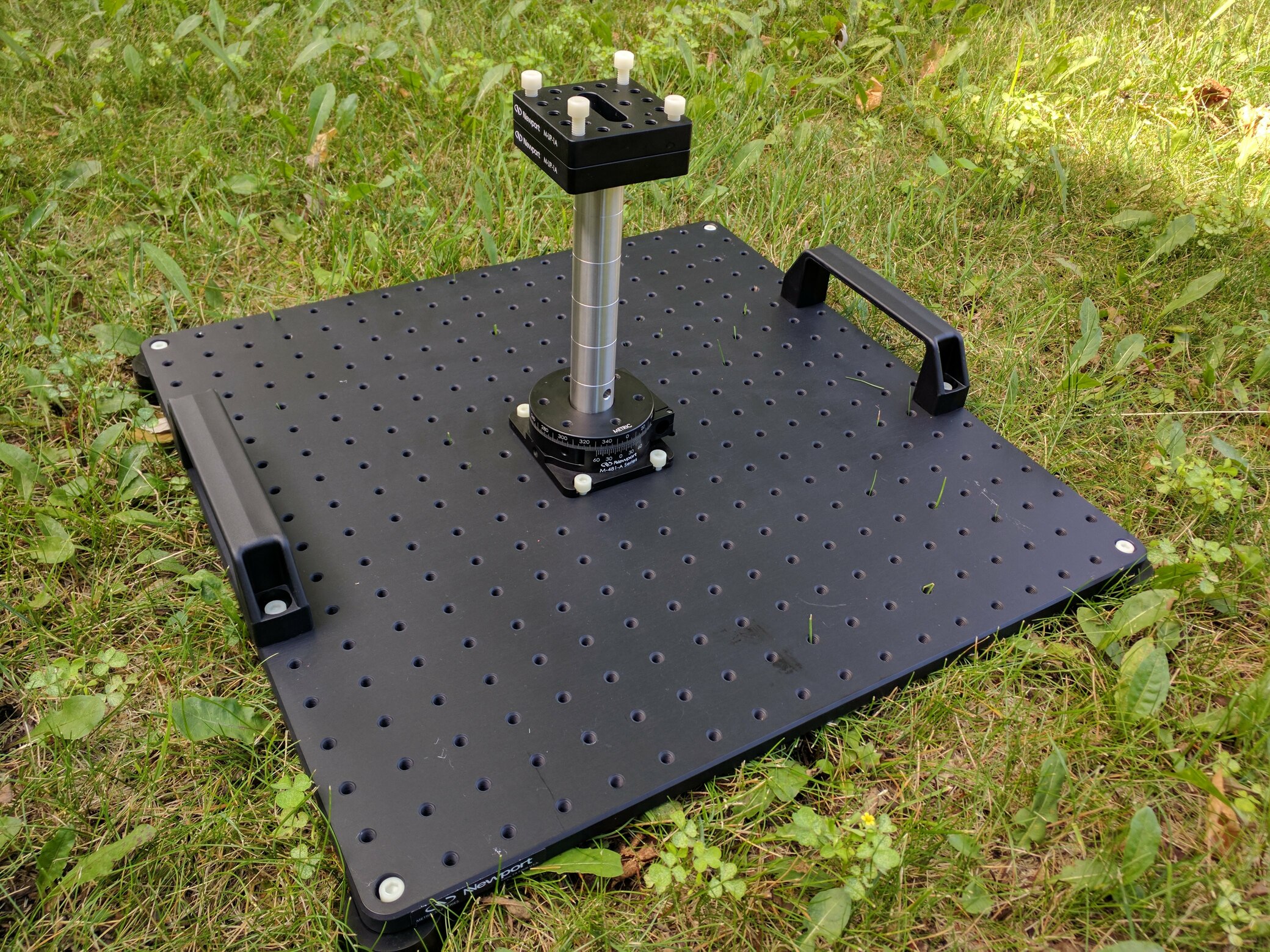
Optical Breadboard Plate | Newport | M-SA2-18X18 | 1 | Solid Aluminum, 450 x 450 mm, 25 mm M6 Grid |
| 5 |  |
Handles, Optical Breadboard | Newport | SA2-HNDL | 1 | 2 Piece Set, SA2 Series |
| 6 |  |
Vibration Isolation Mounting Foot | Newport | M-SA2-FT-70 | 4 | Sorbothane, 70 Durometer, M6 Thread |
| 7 |  |
M6 Nylon Screws, 20 mm long | McMaster-Carr | 97695A114 | 1 pack of 25 | Glass-Filled Nylon Plastic Socket Head Screws M6 x 1.00 mm Thread |
| 8 |  |
M6 Nylon Screws, 25 mm long | McMaster-Carr | 97695A115 | 1 pack of 25 | Glass-Filled Nylon Plastic Socket Head Screws, M6 x 1.00 mm Thread |
| 9 |  |
M6 Nylon Screws, 12 mm long | McMaster-Carr | 97695A113 | 1 pack of 25 | Glass-Filled Nylon Plastic Socket Head Screws, M6 x 1.00 Mm Thread |
| 10 |  |
Nylon Plastic Washer for M6 Screw | McMaster-Carr | 95610A570 | 1 pack of 100 | Size, 6.4 mm ID, 12 mm OD, Off-White |
| 11 |  |
Reusable Threadlocker | McMaster-Carr | 75145A68 | 1 | Vibra-Tite Vc-3, 0.17 oz. Tube |
The assembly notes below are not comprehensive. The purpose of these notes are to explain steps which may not be immediately clear from a visual look at the assembled setup above.
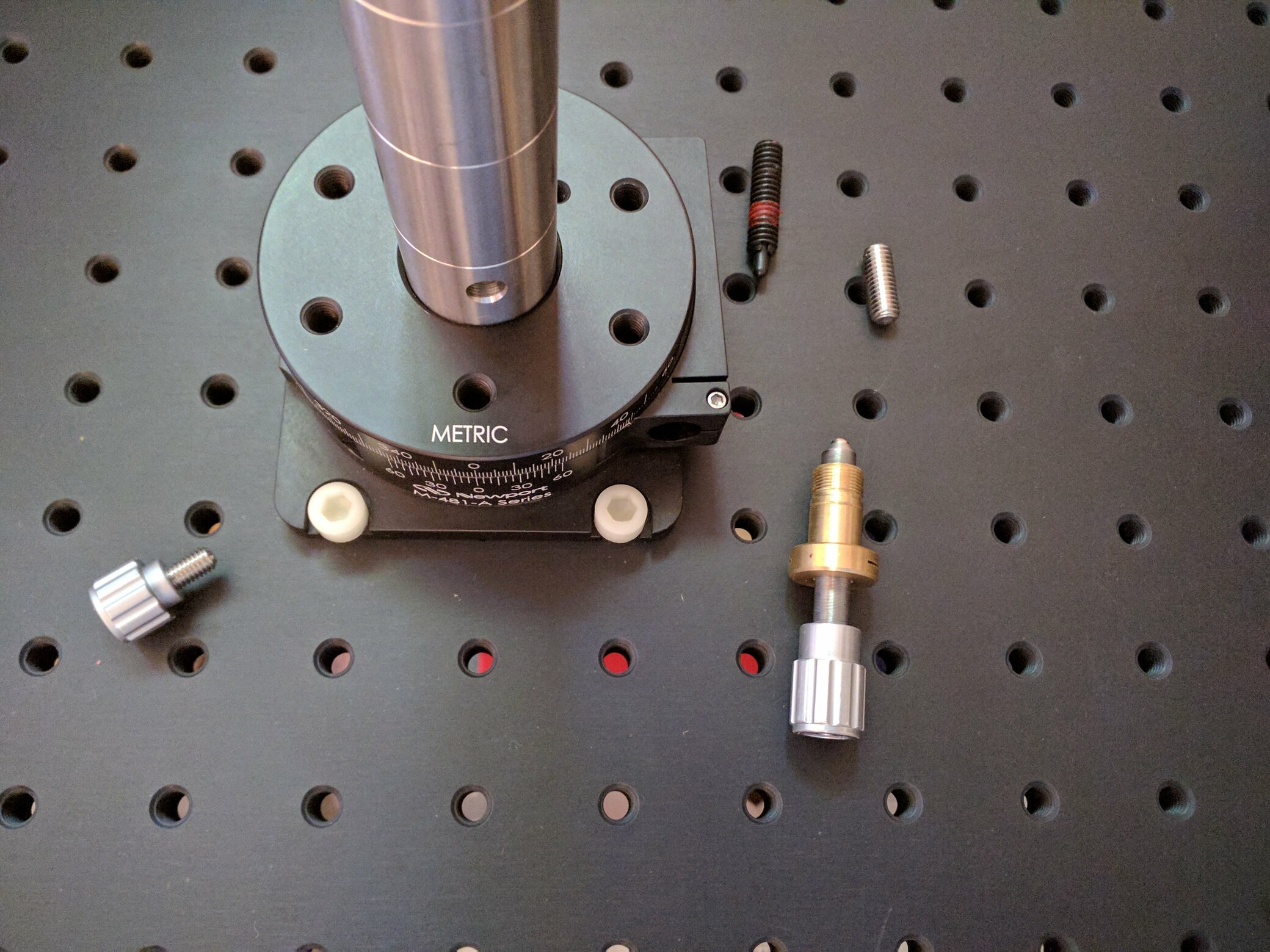
The rotation stage has 4 ferrous parts which can be easily removed, as shown in the image above. A minor amount of ferrous material may be present internally, though it appears small enough to be negligible. Note that removing of the above ferrous parts leaves a mid-stage piece able to rotate. This is known and should not impact the rotation/measurement of the upper or lower-stages. The following was learned about the material makeup of the M-481-A-S through a May 1, 2020 phone call with Newport support.
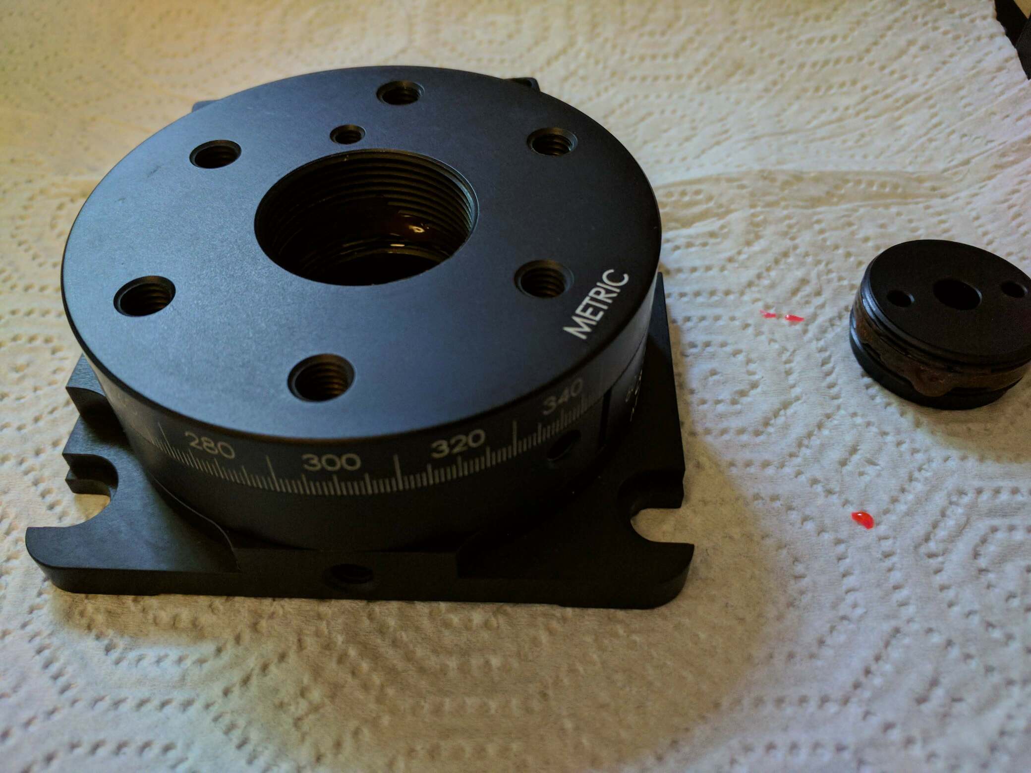
The solid insert screws into the rotation stage until it tight to the bottom. This connection may become loose during rotation testing. Therefore, threadlock is applied to both threads of both connections before installing the solid insert into the rotation stage.
The optical post is held into place by running a M6 nyloc screw from the underside of the solid insert into the optical post.
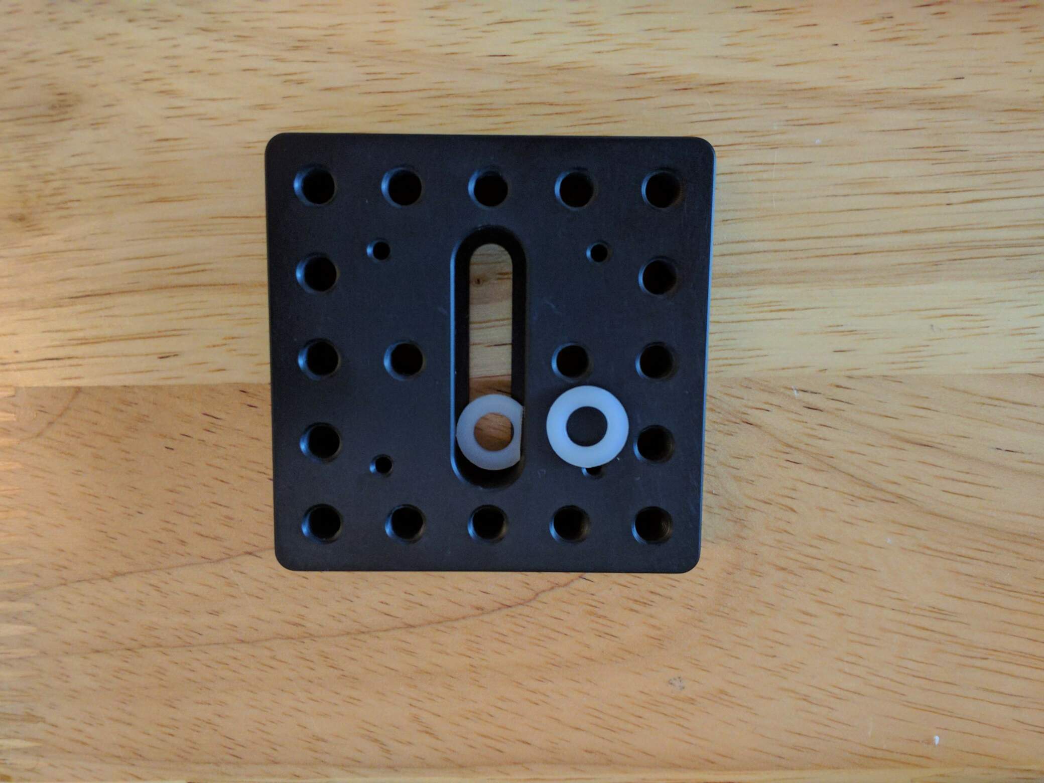
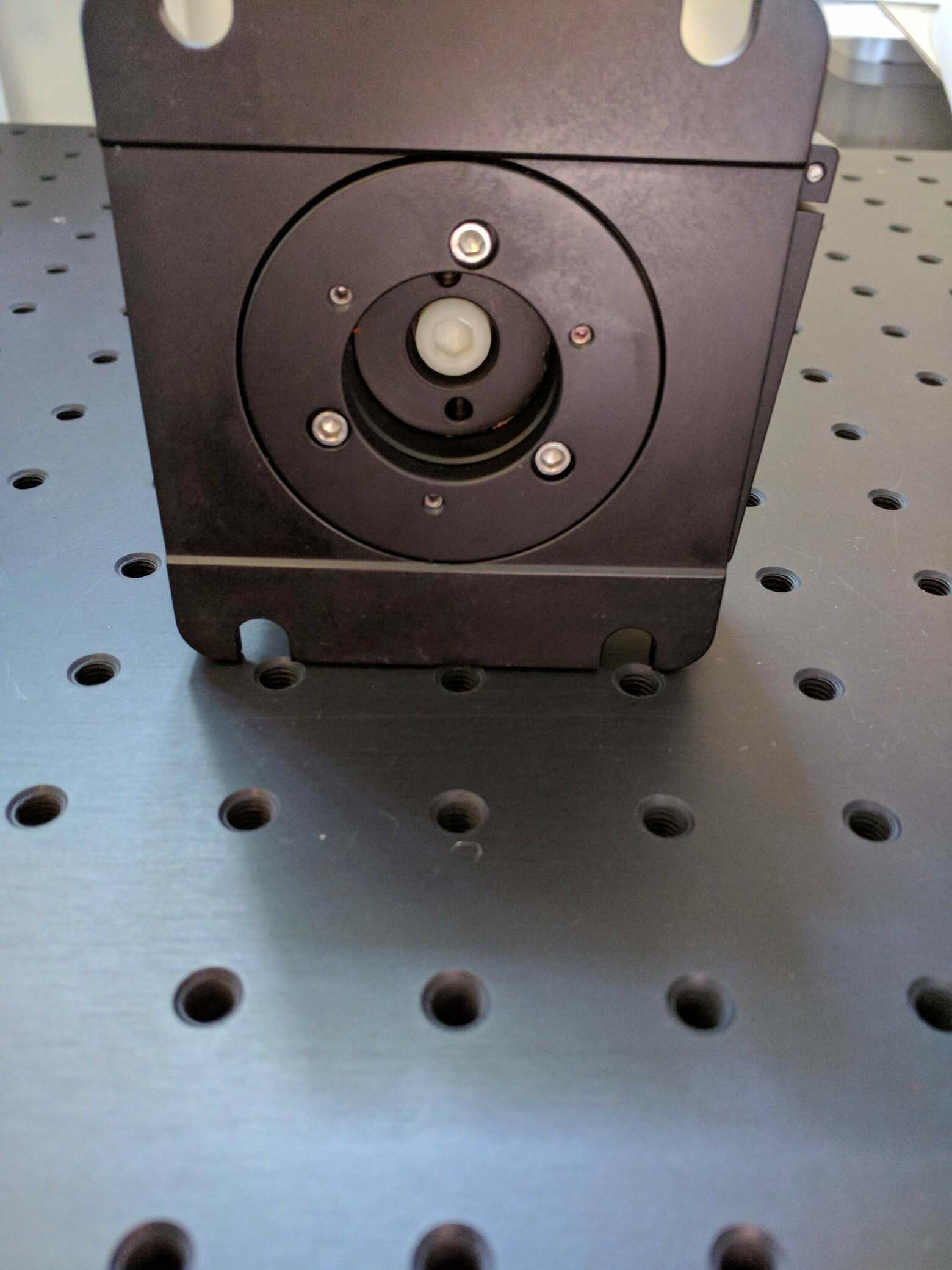
Two mounting plates are used. The lower plate can remain fixed to the optical post while the upper plate can be removed to facilitate mounting the device under test. The lower mounting plate is installed onto the optical post via the center slot shown above. A customized nylon washer can be used when installing the M6 nylon screw. Customization is necessary to fit the washer into the mounting plate slot. The above picture shows the customization which involves removing a section of the washer. A share pair of utility scissors can be used for the customization.
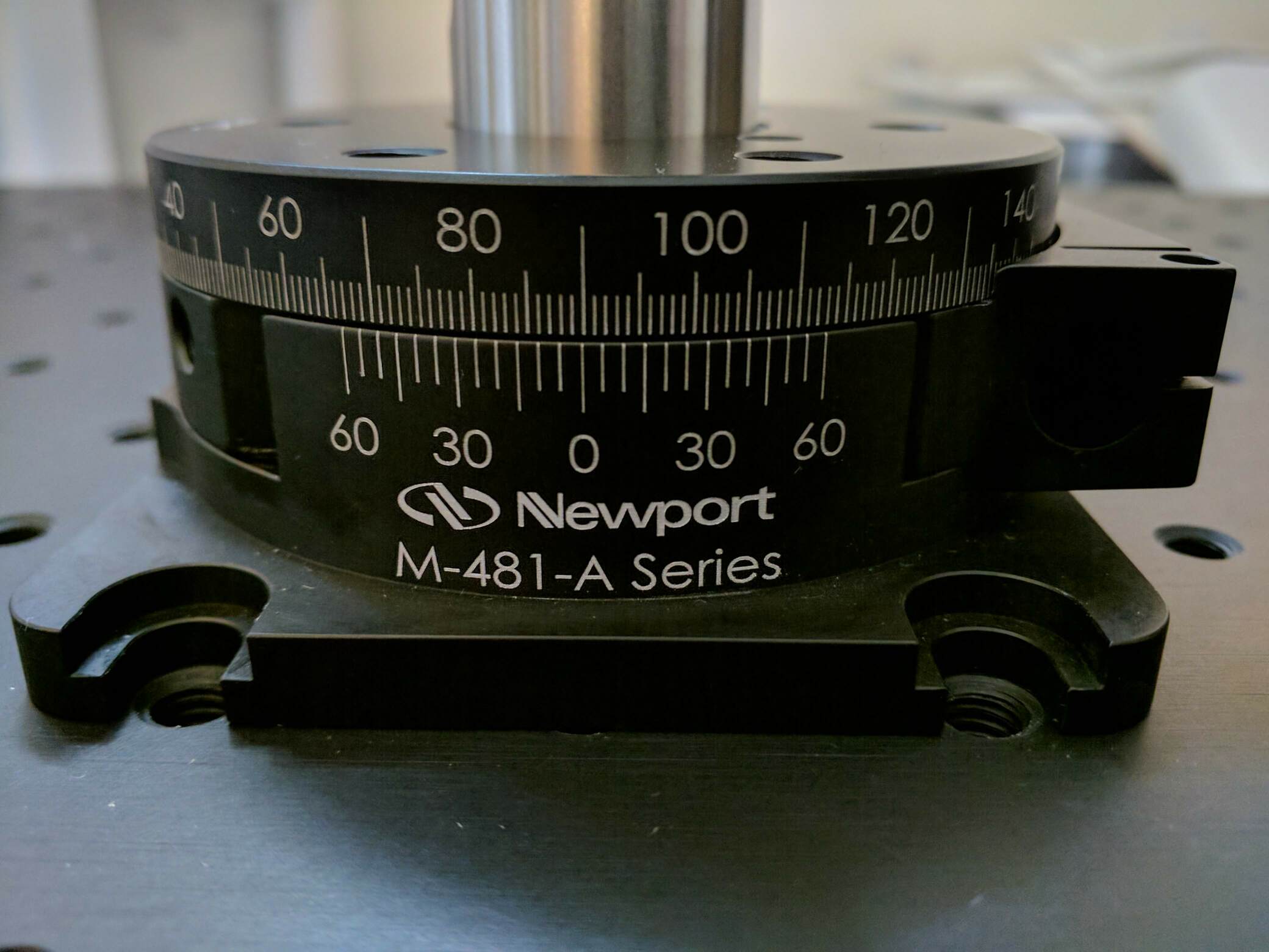
The upper-stage has scale markings indicating every 1-degree. The lower-stage has a vernier with 5 arc min markings.